
Measuring Battery Life On Battery-Powered Medical Devices
By Bob Zollo, Keysight Technologies, Inc. (formerly Agilent Technologies electronic measurement business)
Battery-powered devices are everywhere in medicine, from pacemakers to patient monitoring telemetry to operating room tools. For all of these devices, battery run-time is a key requirement. Any medical professional can easily understand the impact of battery life of the electronic device they are using. Insufficient battery life easily dissatisfies users. In some cases, it could be a matter of life and death. Therefore, extending battery life by lowering power consumption is a main driver for all aspects of the design of medical electronics. Knowing the run-time of your device is important as a means to know if improvements in power management within the device are successful at increasing battery run-time and if your device will meet the demanding needs of its end user.
Considerations For Battery Run-Down Testing
Battery run-time is determined by a battery run-down test. In this test, you run your device — starting with a full battery — and measure the time it takes until it stops working. The time that is measured is the battery run-time. While this is easily said, it is not so easily done, as there are many variables in this test.
Battery Run-Down Test Variables And Solutions

Battery Simulation
Some engineers have considered using a power supply to simulate the battery during a run-down test. To date, this has not been practical. While it may be a hassle to ensure battery state consistency (type and charge), using a power supply to simulate a battery introduces additional variables and test errors.
A standard power supply will not act like the battery, as it will never run down, meaning the run-down test will never reach an end condition. Instead, the power supply will need specialized features to be a battery emulator. Part of the emulation is to have a controllable output resistance and to have excellent transient response with respect to current pulses being drawn by the device. But to fully emulate a battery, the power supply’s output voltage will need drop off as charge is pulled from the power supply into the device during the run-down test. This simulation of draining the battery from full to discharged is challenging, and sophisticated battery models must be employed. If the battery model is not adequate, the results obtained when using the power supply will not match the results obtained when using the battery. Until a good battery modeling solution becomes available, the best way to do a run-down test is to use the real battery, as this will give the exact same results that the end user will experience.
Engineers Want To See More Than Just Run-Time
When designing a device, you will want additional insight into what is happening during the test, beyond just measuring the run-time. This will additionally mean measuring the current being drawn from the battery and the voltage on the battery simultaneously. By plotting voltage and current versus time, a complete picture of a battery run-down is achieved (Figure 1).
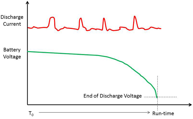
Figure 1: Battery run-down test results
To simultaneously measure battery voltage and current flowing between the battery and the device, you will need two digital multimeters (DMMs), a two-channel data-logger, or a two-channel digitizer. To measure the battery voltage is almost trivial, as the voltage will change slowly. Therefore, a DMM or data-logger making measurements as slow as once per second should be fast enough to capture the slowly decaying voltage waveform. But measuring the current can be a much bigger challenge. In many battery-powered devices, sophisticated power management schemes are used to increase run-time. These schemes turn subsystems on and off for hundreds of microseconds as needed within the device to conserve power. The result is a rapidly changing current waveform that can range from microamperes to amperes. DMMs make integrated measurements that can take hundreds of milliseconds, so they cannot capture a rapidly changing current waveform.
Another issue with using a DMM is burden voltage. When a DMM is configured as an ammeter, the current to be measured is flowed through a calibrated current shunt inside the DMM. The DMM measures the voltage drop across the shunt and calculates the current. The voltage drop inside the DMM reduces the available voltage at the device under test (DUT), and hence places a burden on the circuit. This burden voltage can be hundreds of millivolts (Figure 2).
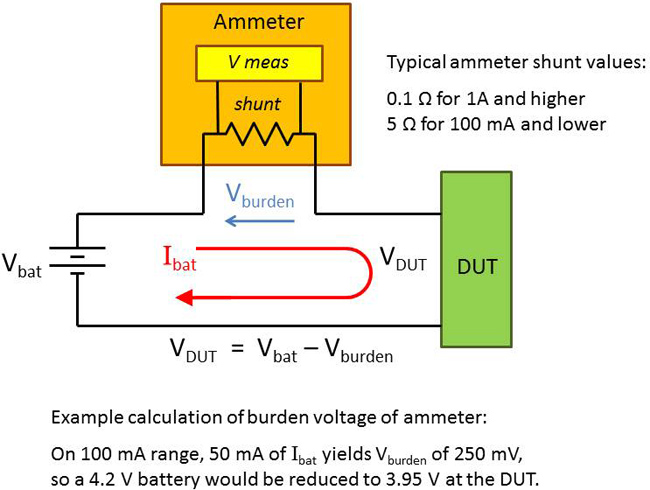
Figure 2: DMM presents burden voltage when measuring current
When trying to measure a rapidly changing waveform over a long period of time, a digitizer seems like the best choice. Digitizers have sufficiently wide bandwidth to capture rapidly changing waveforms, but digitizers don’t directly measure current. Therefore, a current shunt must be used. If the dynamic range of current to be measured is microamperes to amperes, what size shunt should be selected? If the shunt is sized to measure the lowest current accurately, there will be a large voltage drop across the shunt during the high current events, and this will place an unbearable burden voltage on the circuit. If the shunt is sized for the high current, at low currents there may not be enough voltage for the digitizer to measure accurately. Therefore, you may need to compromise on low level current measurement accuracy by selecting a shunt that is suitable for high currents (with acceptable burden voltage drop) and low currents (with a voltage drop that may be at the low limits of the digitizer’s ability to measure).
A Solution For Battery Run-Down Testing
Keysight Technologies offers the N6781A Battery Drain Analyzer and turnkey software for performing run-down tests (Figure 3) for battery-powered devices requiring up to 3 A of current. The N6781A can be configured as a zero-burden ammeter, meaning there is zero voltage drop across the instrument, as it measures current flow between the battery and the device. It offers a unique feature called seamless ranging, so that it can instantly and automatically change range and measure currents from microamperes to amperes at a speed of 100,000 samples per second without losing any data during the range change, making it ideally suited for measuring dynamic currents during run-down tests. Furthermore, it can simultaneously measure the voltage across the battery. With the Keysight 14585 Control and Analysis Software, a battery run-down test can be quickly setup and run-down measurements captured and plotted without writing any software.
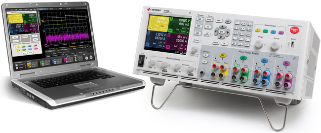
Figure 3: The Keysight N6781A Battery Drain Analyzer and 14585A Control and Analysis Software are a turnkey solution for battery run-down tests on battery-powered medical devices.