
Metallographic Examination Of Medical Implants
Medical technology has developed many new devices that can be implanted into humans (in-vivo) to repair, assist, or take the place of diseased or defective bones, arteries, and even organs. The materials used for these devices have evolved steadily over the past fifty years, with titanium and cobalt-based alloys replacing stainless steels. Metallographic examination has become an indispensable tool in the testing, quality control, failure studies and post-mortem analyses of these devices. This paper presents techniques and results for examination of titanium-based acetabular cups and Co-Cr-Mo femoral hip stems and knees. These implants have porous metallic coatings on one side to enhance bone/metal interface adhesion by in-growth of bone into the porous coatings.
Two variations of acetabular cups were examined in this study. Both used Ti-6% Al – 4% V-ELI (ASTM F-136) as the substrate material. One had commercial purity (CP) titanium fiber metal wire mesh (ASTM F-67) bonded to the substrate for bone in-growth while the other had CP Ti powder bonded to the substrate and tantalum “beads” bonded to the powder to promote interlocking bone in-growth. The femoral hip stem was made from forged ASTM F-799 Co-Cr-Mo and had “beads” of Co-Cr-Mo (ASTM F-76) grade sintered to the surface to enhance in-growth. The femoral knee was also made from Co-Cr-Mo and it had Co-Cr-Mo wire mesh attached.
Sectioning
Ta, Ti and its alloys, and Co and its alloys are difficult metallographic subjects. Co and its alloys are far more difficult to prepare and etch than Ni-base alloys. Refractory type metals, such as Ti and Ta, are noted as being quite difficult to section without introducing damage. They do not have exceptionally high hardness, at least not compared to tool steels and bearing steels, but they are far more difficult to section, grind, polish and etch. Abrasive cut-off blades must have a very loose, weak bond so that they break down at a high rate to continually expose fresh, sharp abrasive to the cut. Blades designed to cut the highest hardness steels do not break down fast enough to section refractory metals without introducing damage. The initial sectioning work was performed with a large abrasive cut-off saw using a blade specifically designed to section refractory metals, such as Ti and Zr. The Co-Cr-Mo components were sectioned with an abrasive blade designed to section superalloys. Properly sectioned specimens exhibit minimal sectioning damage and a fine surface when an abrasive cut-off blade designed specifically for metallographic work is utilized. Introduction of minimal damage in sectioning is the key to successful utilization of modern, simple preparation methods that can be performed quickly.
Mounting
Due to the complexity of the materials attached to the substrates to encourage bone in-growth and create excellent bonding, a number of mounting materials were evaluated. The mounting material must flow into the voids and cavities on the coated side of the implant. For this study, two thermosetting resins, a standard phenolic resin, and an epoxy-based resin, were used. Two cast epoxy resins were used, a very slow curing resin with a viscosity of about 250 cps, and a resin that cures at an elevated temperature and has a very low viscosity of about 25 cps, were used. Vacuum impregnation was used in both cases. The one cast resin cures at 55-75 ºC in about 90 minutes while the other cast resin cures at room temperature in 6-9 h. Finally, a fast-curing acrylic resin was also used; it cures at room temperature in 5-8 minutes. To insure absolutely perfect edge retention, specimens (all but one) were mounted in the hot-mounting epoxy-based resin after electroless-nickel plating prior to encapsulation.
Preparation Methods
Numerous approaches could be used to successfully prepare these specimens. Only one preparation cycle, however, was used for the titanium-based acetabular cups and only one method was used for the Co-Cr-Mo femoral hip stems and knees. These methods were chosen based upon past experience with these alloys1. Table 1 lists the details of the preparation method for the Ti acetabular cups. The four-step method was chosen over the usual three-step method1 to be more conservative. Since this work, additional specimens have been prepared equally well using the three-step method, as discussed below.
Because this sectioning approach introduced minimal damage and produced a reasonably smooth surface, rough grinding is unnecessary. If the mounts are carefully made, and placed in the holder so that the bottom face is perpendicular to the holder wall, grinding can commence with a relatively fine grit size SiC paper. One grinding step with 320-grit SiC is usually adequate. The next step employs 9-µm diamond on a silk cloth. This cloth produces a decent removal rate with an excellent surface finish while imparting minimal damage. Always charge the cloth with diamond paste and add a petroleum-based lubricant before commencing polishing. During the polishing cycle, add a small amount of 9-µm diamond in suspension form, about every 30 s to keep the cutting rate high. If the polishing head rotates at <100 rpm, and it can be set in “contra” mode (head rotates clockwise while the platen rotates counterclockwise), the slurry will stay on the cloth better, and less diamond needs to be added. At higher rotation speeds, the diamond may be splattered around the lab walls in contra mode, depending upon the polisher design. In complementary mode (head and platen both rotate counterclockwise), the liquid polishing suspensions are rapidly carried off the platen and down the drain due to centrifugal force. The faster the platen and head speed, the more rapidly the suspensions go down the drain.
The three-step method for Ti utilizes steps 1, 2 and 4 in Table 1. But, in the three-step method, the 9-µm step and the final step are continued for 10 minutes. When four-steps are used, these two steps are shorter, 4 or 5 minutes is adequate, and a finer diamond polishing step is added. For this work, a silk or a synthetic cloth can be used with 3-µm diamond (use the diamond in the same way as in the 9-µm step). The loads listed are per specimen; either individual force loading or a central force loaded holder can be used.
Table 1 - Four-Step Preparation Method for Titanium Implants
Note: Charge cloth with diamond paste, work it into the cloth surface and add a lubricant. Periodically add a small amount of diamond suspension of the same particle size to keep the cutting action high.
When a polyurethane pad is used for the final polish, the pressure must be substantially higher (as shown in Table 1) than with a flocked cloth to avoid relief. With a flocked cloth slightly lower pressures, either 5 or 6 lb/specimen (22 or 27 N/specimen) are used without relief problems. Attack polishing is used for the last step. Hydrogen peroxide (30% conc.), which has no environmental problems, is mixed with colloidal silica and is a very effective final polish for Ti and its alloys. The three- and four-step methods produce excellent polarized light response with CP Ti (hcp crystal structure).
For the Co-Cr-Mo specimens, a slightly different process was used, as shown in Table 2. The first step used a fixed grinding disc with 125-µm diamond embedded in the disk. A diamond grinding disc with a somewhat finer diamond size, e.g., 70-µm, could also be used. The next step was 320-grit SiC paper. As all of the preparation work was performed with an automated grinder/polisher with six specimens in the holder (central force holder), each sheet was used for only one minute. Individual force loading can also be used.
Table 2 - Five-Step Preparation Method for Co-Cr-Mo Implants
Notes: 1. Charge cloth with diamond paste, work it into the cloth surface and add a lubricant. Periodically add a small amount of diamond suspension of the same particle size to keep the cutting action high. 2. Start polishing with colloidal silica (mix 6 parts of colloidal silica with 1 part H2O2, 30% conc); after 2 minutes, flush off the abrasive with water and continue polishing with 0.05-μm alumina. 3. Follow with a 1 h polish using a vibratory polisher with 0.05-μm alumina on a flocked cloth.
The second and third steps are similar or identical to those for Ti. The fourth step was also similar, although shorter in time but with a duplex abrasive approach. Slightly greater pressure was used with the polyurethane cloth. Polishing commenced using the same attack polishing procedure; but, after 2 minutes the abrasive was washed off and replaced with alumina abrasive slurry. The specimens were washed, dried and examined. Then, they were placed on a vibratory polisher using a flocked pad and a slurry of alumina abrasive. After one hour they were removed, washed and dried.
Etching
Commercial-purity titanium can be examined in polarized light in the as-polished condition to study the grain structure. This does not work with Ti-6Al-4V, however, as it is an α-β alloy. Kroll’s reagent is the most commonly used standard etchant for Ti and its alloys. For color work, a modification of Weck’s reagent (100 mL water – 25 mL ethanol – 2 g NH4F·HF) can be used; examination with polarized light and sensitive tint enhances the results.
Co alloys are more difficult to etch than Ni-base alloys and the Co-Cr-Mo alloy is extremely corrosion resistant and very difficult to etch. Beraha’s color etches for Co 2 did not work on this alloy.
Results
Very small burn marks were observed on some of the Ta beads, as shown in Figure 1. Kroll’s reagent revealed the burn on the Ta beads, but did not bring up any other aspect of the Ta bead structure. Consequently, additional sections were made using a precision saw and a diamond blade at 3400 rpm, with a feed rate of 4 mm/min. Specimens were mounted using three of the resins (the epoxy-based hot mounting resin [not plated], the phenolic hot mounting resin and the elevated temperature curing cast epoxy resin) and polished with the three-step method1. No burns were observed. An example of one of these specimens is given in Figure 2.
Regarding the mounting materials used, only the acrylic produced really noticeable edge rounding. Figure 3 presents examples of the edge rounding. Some staining problems, due to bleed out of liquids from the shrinkage gaps, were also encountered using the acrylic mounting medium. Bleed out and staining problems were not encountered in the specimens prepared with the other four mounting materials.
Examples of the microstructure of the two types of acetabular cups are presented in Figures 4 and 5. Examples of the structure of the femoral hip stem and the femoral knee are presented in Figures 6 and 7.
Conclusions
Sectioning of Ti and Co alloys is difficult but can be accomplished using an abrasive blade designed for metallographic sectioning of these alloys. These abrasive blades produce as little damage as possible, for an abrasive blade, and yield smooth, flat surfaces. The Ta beads, however, exhibited small burn marks when cut with this blade. The diamond blade used with the precision saw sectioned all materials, including the Ta beads, without any observable burning and with minimal damage. The precision saw, although limited to cutting smaller diameter pieces, and somewhat slower in cutting speed, produces even less damage than the best abrasive cut-off wheel.
Mounting with the epoxy-based hot mounting resin produced superb flatness. Very fine particles of this resin were placed around the specimen. The very fine particle size of this resin enabled it to flow better into the powder, wire or beads attached to the substrate yielding excellent edge retention. The Bakelite phenolic resin also produced good results. Both cast epoxy resins yielded good results, but with very minor edge rounding. Plating the specimens with electroless nickel yielded superb edge retention, but is not required, as long as the preparation method uses the fine epoxy-based hot-mounting resin and modern, hard-woven, flat cloths, rather than napped cloths, that are used in the diamond polishing steps. Acrylic resins are really inadequate for this type of work.
The polishing methods yielded excellent, scratch-free, damage-free surfaces suitable for color metallography, at least for the Ti acetabular cups. Beraha’s color etch for Co-base alloys did not produce an interference film on the specimen surface that would create color, so only “black and white” etchants could be used. However, the preparation results for the Co-Cr-Mo specimens were excellent.
Figure 1 - Two examples of slight cutting damage to the tantalum beads bonded to the CP Ti powder that was bonded to the Ti-6Al-4V substrate of the acetabular cup, Krolls reagent (magnification bars are 50 µm long).
Figure 2 - Two examples of the CVD tantalum bead structures on the Ti-6Al-4V acetabular cups sectioned with the precision saw using a diamond wafering blade, 3400 rpm and a feed rate of 4 mm/min (100x). No damage to any bead was detected.
Figure 3 - Examples of (left) loss of edge retention for the Co-Cr-Mo femoral hip stem with Co-Cr-Mo beads mounted in the acrylic resin; and, of (right) edge rounding and staining (bleed-out) for the Co-Cr-Mo femoral knee with Co-Cr-Mo wire attached (etched with HCl-H2O2). The magnification bars are 200 and 50 µm long, respectively.
Figure 4a - Microstructure of the acetabular cup made with a Ti6Al4V substrate (top) and CP Ti wire mesh (bottom) diffusion bonded to the substrate. The specimen was mounted in the Bakelite phenolic resin and etched with modified Weck’s reagent (50X).
Figures 4b and 4c - Microstructure of the acetabular cup with a Ti6Al4V substrate and CP Ti wires diffusion bonded to the substrate. This specimen was electroless-nickel plated and then mounted in the fine epoxy-based thermosetting resin and etched with modified Weck’s reagent. Note the perfect edge retention (50 and 100x, respectively).
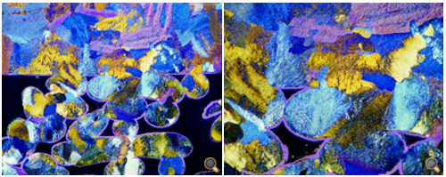
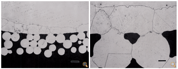
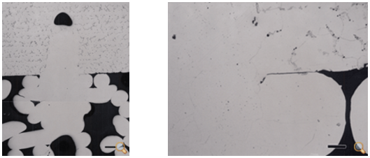
Figures 5a and 5b - Microstructure of the acetabular cup with the Ti6Al4V substrate, CP Ti powder bonded to the substrate, and Ta beads attached to the powder (shown in a only). The specimen was mounted in the fine epoxy-based thermosetting resin (it was not electroless Ni plated) and was etched with modified Weck’s reagent (50 and 200x, respectively).

Figures 5c and 5d - Microstructure of the acetabular cup with a Ti6Al4V substrate with CP Ti powder diffusion bonded to it and Ta beads attached to the powder (not shown in these images). Left: porous nature of the CP Ti powder and its bond to the Ti6Al4V substrate (50x); right: view of the grain structure and pores in the powder (500x) (Kroll’s reagent).
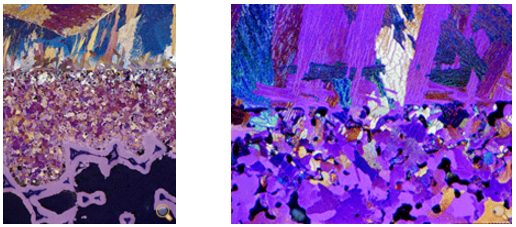
Figures 6a and 6b - Microstructure of the forged CoCrMo femoral hip stem with diffusion bonded CoCrMo beads. The specimen was mounted in the Bakelite thermosetting resin and etched with HCl and H2O2 (magnification bars are 200 and 50 µm, respectively.
Figures 7a and 7b - Microstructure of femoral knee with CoCrMo substrate and CoCrMo wire bonded to it. The specimen was mounted in the low-viscosity epoxy resin that cures at 55-75°C and was etched with HCl-H2O2. Note that, although the substrate was etched, the wire was not. The view at the right shows an enlarged view of the bond between the substrate and wire. The magnification bars are 200 and 50 µm, respectively.
About The Author
George Vander Voort has a background in physical, process and mechanical metallurgy and has been performing metallographic studies for 48 years. He is a long-time member of ASTM Committee E-4 on metallography and has published extensively in metallography and failure analysis. He teaches MEI courses for ASM International and is now doing webinars. He also is a consultant for Struers Inc., and will soon be teaching courses for them.
Resources
- G.F. Vander Voort, Buehler’s Guide to Materials Preparation, Buhler Ltd., Lake Bluff, Illinois, 2004.
- E. Beraha and B. Sphigler, Color Metallography, American Society for Metals, Metals Park, OH, 1977
This article reprinted courtesy of its original publisher, Vac Aero International Inc.