
The Most Misunderstood Problem In Medical Injection Molding — And How To Solve It
By Travis A. Belz, Sr. Plastics Engineer, Beaumont Technologies, Inc.
Shear heating variations are a primary cause of numerous issues that are common when injection molding medical parts, including high scrap rates, weight and dimensional variation between cavities or between shots, long cycle times, warpage, and others. Yet more often than not these shear heating variations go unchecked, usually due to misunderstandings regarding shear heating in medical injection molding. This article will explain how shear heating develops, how it affects your parts, and how to control it to your advantage.
An Introduction To Shear Heating
The injection molding industry has been around since the early 1870s, and since that time, shear heating variations have been an epidemic upon the trade. The problem may very well be the most misunderstood and overlooked issue in the injection molding industry today. Understanding this issue is paramount to successfully injection molding medical parts, with their generally abstract shapes and very tight tolerances.
As the term implies, shear heating (also referred to as frictional heating) is defined as a temperature rise due to friction. To understand the concept, place your hands together and rub them back and forth quickly until you feel heat. This is heat due to friction. This same phenomenon also occurs in injection molding, only at much higher temperatures.
Shear heating occurs as plastic (both thermoplastics and thermosets) flows through a mold’s runner system. As the different layers of plastic slide past each other, it heats up due to the tremendous pressures placed upon it in order to make the material flow. The heat increase that takes place is not uniform however, as seen in Figure 1.
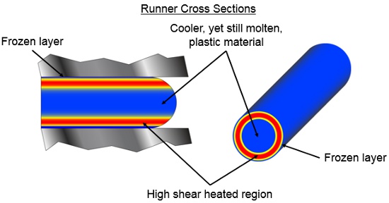
Figure 1: Temperature difference in runner cross sections
Notice that the shear heating occurs near the outsides of the runner channel, just inside a thin frozen layer of plastic that develops as plastic melt comes into contact with the cold steel wall and freezes. Meanwhile, there is almost no shear heating whatsoever at the center of the runner channel. While it is impossible to accurately measure the temperature difference across a runner channel during the molding process, simulations and applied research suggest that the difference in temperature may be as high as 100° to 300° F. An intense difference.
Plastic is a non-Newtonian fluid, which means that as shear rate increases, viscosity decreases. The lower a viscosity of a fluid, the easier it flows. Simply put, the hotter the plastic melt, the easier it will flow. Referring back to Figure 1, the hotter plastic is at a lower viscosity, which means it will flow more easily than the cooler plastic.
This shear heating phenomenon becomes even more interesting when the material arrives at a branch (an intersection) in a runner system. Plastic flows in a laminar manner, which means that it flows with zero turbulence. Due to this fact, it is possible to predict the direction in which various laminates of plastic will travel. When plastic reaches a runner branch, the material splits and will flow in both directions, with the hotter laminates staying to one side of the runner channel, and the cooler ones flowing to the opposite side. Figure 2 illustrates this behavior. Now there is a distinct separation of different temperature plastic from one side of the runner channel to the other.
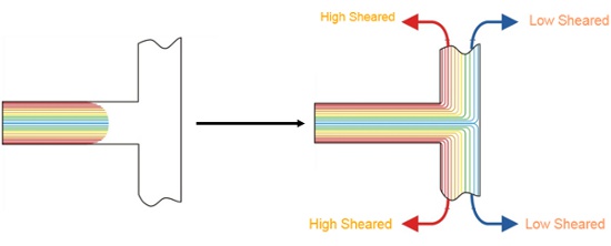
Figure 2: Temperature difference across a runner channel before and after a branch
This thermal variation begins to become a problem, especially in multi-cavity molds. As plastic continues to flow through a runner system, the hotter plastic eventually comes to rest at a very specific location within a cavity. As shown in Figure 3, in this common mold design the plastic must flow through two intersections to make it to any of the cavities. The plastic laminates that reach the four inside cavities (those closest to the sprue) have received the majority of the shear heating, and thus are filling more quickly than the four outside cavities. The hotter plastic is less viscous so it can flow with more ease, while the cooler plastic is more resistant to flow. This results in the filling imbalance we see in Figure 3.
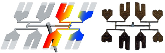
Figure 3: Filling imbalance due to shear heating
The Negative Effects Of Shear Heating
This thermal filling imbalance is the source behind so many of the troublesome issues experienced in injection molding, which are particularly problematic in medical injection molding. Following scientific molding practices, the process should switch from filling to packing pressures when the parts are approximately 95 to 99 percent filled. The question is, which cavities?
If the process is transferred when the four inside cavities are 95 percent filled, then the process conditions within outside cavities will suddenly and dramatically change. This will increase the potential for problem scenarios such as short shots, sinks, voids, or a combination of these effects within the outside cavities. If the process is transferred when the outside cavities are 95 percent filled, the potential for flash and over packing throughout the inside cavities increases.
Problems like these are just the beginning. Put simply, when there is an imbalance in a tool, there is variation in the final parts produced from different cavities. Common issues that result from imbalanced conditions are variations in size, variations in weight, warpage, high scrap rates, unnecessarily long cycle times, narrow process windows, dimensional instability between parts, etc. Shear heating variations occur in both hot and cold runner systems.
Figure 4 shows a typical dimensional scatter of data from a 16-cavity mold, with high and low control levels for a critical dimension. While most of the data points fall within an acceptable range, a few lay outside or very close to both the top and bottom control levels. This problem often occurs when molding.
It is also a problem that is very difficult, if not impossible, to solve through process changes. The reason for this is that all the cavities change when altering a process, not just the one that is problematic. For example, using the data in Figure 4, if packing pressure or time is reduced to bring the cavities that are too high (1, 7, and 8) down to an acceptable level, then all the cavities will experience less packing. This would cause the dimensions of all the cavities to decrease, including the cavities with dimensions that are already too small (6, 11, and 14). For this reason, balance problems generally cannot be fixed with process changes, an approach that the industry often attempts.
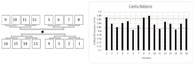
Figure 4: Data on a critical dimension from a multi-cavity mold with high and low control levels shown
Taking another look at the same data with the shear heating variations concept applied, it can now be seen that the source of the problem is an imbalance due to shear heating variations. Figure 5 shows the same data as Figure 4, only rearranged by color coding according to which cavities receive an equal amount of shear heated plastic. For instance, the four cavities marked as red were fed by flowing laminates with the same shear heated plastic and are therefore expected to be similar to each other. Cavities marked in blue will also be similar to each other but different from the red cavities, due to the different temperature plastic that filled these cavities. The same goes for the cavities marked in green and orange.
By evaluating the data this way instead of the traditional method, it is much more apparent that the problem is, in fact, due to shear heat variations. Four distinct groupings are apparent. The cavities in red were filled by high temperature, low viscosity plastic, and so are better packed out and exceeded the high control line. The cavities marked in green were filled with a plastic that experienced less shear heating and are below the lower control line. By reviewing the data in this grouping method, it becomes much simpler to see where the source of the problem originates.
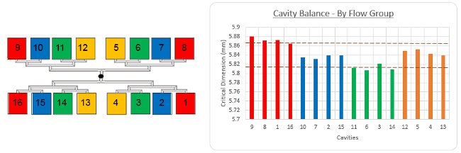
Figure 5: Data on critical dimension organized by flow group
Shear heating variations can be a problem with single cavity molds as well. A common example is shown in Figure 6. Due to laminar flow, the hotter plastic flows only along the outside edges of the part. Notice how the outer edges of the part are more filled due to being filled by a hotter, lower viscosity plastic melt, while the center of the part is lacking due to being filled by a cooler plastic melt. This often results in gas traps, warpage issues, and dimensional instability — problems that are very difficult to mitigate with process changes.
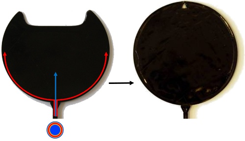
Figure 6: Shear heating affecting the filling pattern of a single-cavity mold
Methods For Addressing The Shear Heating Problem
Although several different approaches for correcting for shear heating variations have been attempted throughout the years, most have proven unsuccessful. Varying the sizes of runners and gates, otherwise known as artificial balancing, is one such approach. While popular, this method has proven difficult to control and is somewhat unpredictable. In fact, artificially balancing really only covers up the problem — it will never solve shear imbalances. The approach still results in variations within the parts, because artificial balancing cannot stop different temperature plastic from reaching different cavities. Once the gates and runners have been artificially balanced, any small process change can alter the filling balance of a mold, which will still result in part-to-part differences.
Another method that is often used when trying to balance a mold is the process itself. Typically, injection speed changes or cooling temperature increases or decreases are applied to try to improve a mold’s filling balance. While injection speed does contribute to the degree of shear heating, it is still impossible to separate out different speeds into different cavities. Changing the process to improve shear heating variation often leads to a processor chasing their own tail, a very tight process window, and usually only a slightly improved balance, if at all. None of this addresses the key issue of thermal variation.
Beaumont Technologies Inc. has designed and patented a method for controlling and eliminating shear heating variations with a runner technology called MeltFlipper. This technology was developed for the very purpose of eliminating shear variations in single and multi-cavity molds. The technology works by manipulating the flow path of the highly sheared plastic such that the higher temperature plastic is evenly shared across all cavities within a mold, or strategically placed at a specific location of a single cavity mold.
Figure 7 illustrates how MeltFlipper can alter the filling pattern of a single-cavity mold. This example shows the difference in filling pattern on the same mold with and without MeltFlipper technology. Without MeltFlipper, the hotter plastic travels along the side of the cavity, resulting in a gas trap or weld line. For this application, MeltFlipper was designed so that the hotter plastic is driven through the center of the part, effectively changing the filling pattern so there is no chance of a gas trap or weld line. Furthermore, the location of the hotter plastic affects the warpage — the part on the left is expected to warp differently than the part on the right.
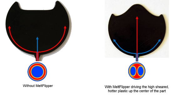
Figure 7: Difference in filling pattern without and with MeltFlipper
MeltFlipper works in a similar way with multi-cavity molds, except that instead of changing a filling pattern with a single cavity, now the goal is to evenly share the high shear plastic to all cavities. With all cavities filling at the same time and uniform material properties filling each cavity, variations within the parts, mold, and process are minimized.
Shear heating variations exist within every mold that has ever been built and occurs every time a mold is shot. Understanding how shear heat develops, how it leads to an imbalance, and also how it can be controlled are paramount to improving the quality and productivity of medical injection molding applications.
 About The Author
Travis A. Belz is the senior applications engineer at Beaumont Technologies, an injection molding technology, training, and consultancy company located in Erie, PA. He received his B.S. from the Penn State Plastics Engineering program in 2007. Previously, Travis worked for Multi-Plastics, Steris, and Advantage Puck Plastics, all in engineering roles overseeing injection molding projects from concept to production.
About Beaumont Technologies
Beaumont Technologies (www.beaumontinc.com) , a pioneer and world leader of in-mold rheological control technologies, invented and holds patents on MeltFlipper and other injection molding technologies. Beaumont is also a world-class simulation, plastics training, and injection molding consulting provider. The company is headquartered in Erie, PA, and was founded in 1998.