
Using Relational Risk Analysis To Control Procedure Failures In The Bio/Pharma & Medical Device Industry
By Mark F. Witcher, Ph.D., biopharma operations subject matter expert

In the bio/pharma and medical device industries, operating procedures guide virtually every activity and are required for compliance with good manufacturing practices (GMPs). Minimizing procedure execution failures is critical to the success of every manufacturing enterprise.
This article describes how relational risk analysis (ReRA), introduced in my previous article here, can be used to quickly and efficiently analyze and minimize the probability of procedural failures, especially those due to human errors. A human error is defined as a person not correctly performing a task as a result of failing to adequately follow one or more instructions. The instructions can be a written step or sequence of steps in a manufacturing or standard operating procedure (SOP), verbal commands, or any other instruction necessary to complete a critical function required for reaching an objective.
Executing a ReRA while writing the procedure can greatly improve the quality of the procedure by identifying critical steps that may be susceptible to failure. When vulnerable steps are identified, the methods by which the steps are executed can be modified to reduce the probability of failure, frequently by controlling outside factors that might increase the probability of the step’s failure. In addition, if the ReRA’s results are included within the procedure, operators can be informed of critical steps that might have an increased risk of failure so they can be more focused on successfully completing those steps.
A Basic ReRA System Risk Structure (SRS) For A Procedure
ReRA is based on defining a risk as a probabilistic cause event–system–effect event relationship described in Figure 1.1 ReRA focuses the analysis on the risk’s mechanism of action, defined as the system instead of focusing primarily on the risk events. The figure describes the procedure or a step in the procedure as a single-system SRS (system risk structure) benefit risk, with a human operator as the primary element of the system. While the system for a harm risk is designed to prevent the propagation of the risk’s sequence of events, a benefit risk’s system, such as those required for executing a procedure, must be designed to maximize the probability of propagating the sequence of the procedure’s events to assure the maximum probability of successfully reaching the procedure’s objective.

Figure 1: SRS for a procedure or a step in a procedure – A ReRA model for a benefit risk of an input cause event to an execution system that propagates the cause event to produce either a successful execution event or a failure event.
The system includes the procedure’s instructions, the operator performing the procedure, and any equipment required to complete the procedure. The design objective of the system is to maximize the probability of success while controlling the impact of secondary factors that might compromise the system’s probability of success. Figure 1 uses the following symbols:
- LC – Probability of a cause or initiating event or command to execute a procedure. In most cases, the procedure is initiated deliberately, thus the probability of the initiating event is certain LC = 1.
- LE – Probability of the procedure’s successful execution.
- ⌐LE – Probability of the procedure not being executed properly.
- SysLP – Probability of the system successfully executing the procedure.
- ΔSysLP – The amount SysLP is changed by a secondary cause event or factor with a probability of occurrence of 2LC.
The probability of the instruction’s successful execution LE is calculated as the mathematical product of SysLP and LC. If the execution is unsuccessful, the failure has a probability of 1 – LE = ⌐LE of occurring.
To facilitate the discussion, likelihoods will be represented by rating values using the table in Appendix A. Ratings are identified by a “^” symbol. Note that LX =1 (certain) is represented by LX^ = ≥7 (essentially certain); LX = 0.5 (50%) by LX^ = 0; and LX = 0 (impossible) by LX^ = ≤ -7 (essentially impossible).
Using ReRA’s basic principles, the system risk structure (SRS) in Figure 1 can be used to evaluate the likelihood of achieving the procedure’s objective by answering the following three sets of questions:
- Under normal conditions, estimate, using Table A, the likelihood SysLP^ of the execution system successfully achieving the objective. Given the severity SE of not achieving the objective, is the likelihood acceptable?
- What secondary factors or threats might reduce SysLP^ by at least one order of magnitude if they occur. Estimate the likelihood 2LC^ of the secondary threat occurring. Is ΔSysLP^ given 2LC^ acceptable? If not, what system modifications or efforts to control the factor are required to make SysLP^ acceptable?
- What secondary factor opportunities are available to increase SysLP^ by at least one order of magnitude and how can it be implemented? Is the cost of implementing the opportunity justified by the improvement in the system’s performance?
The answer to each question should include a rationale for the estimate, including supporting information. In addition, the rationale should include a discussion of whether the estimate is based on enough information and experience to be reasonably valid. If not, where can additional information or experimental data be obtained?
A More Comprehensive Execution SRS
For important steps, a more detailed analysis SRS can be created by subdividing the system shown in Figure 1 into three separate subsystems as shown in Figure 2. Each subsystem plays a role in accomplishing many objectives related to executing a procedure step or sequence.

Figure 2: A more complete SRS for modeling a procedure step.
The benefit risk system shown in Figure 2 expands the risk model to include three sequential subsystems for better estimating SysLP and secondary factors for each subsystem. The first two subsystems are best evaluated as benefit risks, with SOPLP and HUMLP evaluated as probabilities of success. The third subsystem is best evaluated as a harm risk by estimating the probability of failure, with the EQPLP converted to a probability of not failing ⌐ EQPLP by using the relationship ⌐LX = 1 – LX, or in the case of ratings, using ⌐LX^ = – LX^.1
A risk analysis would assess the baseline value of each subsystem’s likelihood of success SysLP as well as the secondary factors ΔSysLP that might either degrade or improve each subsystem’s probability of success. An expanded discussion of secondary factors is provided in Appendix B.
The three subsystems are:
- Instruction subsystem (SOPLP^) – The probability of the instructions are clearly stated and properly structured so as to be clearly understood by a minimally capable operator. Are the instructions well defined and clearly presented in the correct sequence to the operators?
- Operator subsystem (HUMLP^) – The probability of the human operator receiving the instructions, correctly interpreting their meaning, and successfully executing the instructions to achieve the objective. What could distract or interfere with the operator’s ability to execute the instructions?
- Equipment subsystem (EQPLP^) – Frequently, executing a step requires the use of a tool (e.g., torque wrench), equipment (e.g., laminar flow hood), or instrument (e.g., pH meter) that might have a meaningful failure rate impacting the success of the procedure. The failure rate rating, typically much less than 50%, must be translated into a success rating by taking the negative of the estimated failure rating.
The three subsystems are modeled as a sequence where the success of the entire system depends on the success of each subsystem. Using the probabilities or probability ratings shown in Table A in the Appendix of this article, the overall SysLP can be calculated as the mathematical product of the probabilities. If ratings are used, then the overall rating of a benefit risk can be approximated as the minimum of the three sub-risk rating values.
The risk register (RR) format shown in Table 1 can be used to document a procedure’s ReRA for the SRS shown in Figure 2.

Table 1: A risk register format for documenting the ReRA analysis for the procedure or procedure step shown in Figure 2. The RR for an SOP or larger procedure could be used for each step or set of combined steps. Ratings in the table are for illustration purposes only.
The SRS shown in Figure 2 is useful for examining each step for the factors that could influence the step’s performance. However, for many steps, one or more of the subsystems will have a high likelihood of success and therefore would not significantly impact the step’s SysLP.
To execute a detailed ReRA of a procedure, each step or logical combination of steps would be analyzed using the SRS shown in Figure 2 to produce an RR shown in Table 1. If the results of Table 1 are shown or summarized within the procedure, operators, especially operators executing the procedure for the first time, would be informed of the step’s risks.
Reference
- Witcher, M.F., Relational Risk Analysis For The Bio/Pharma Industry, BioProcess Online, January 29, 2024. https://www.bioprocessonline.com/doc/relational-risk-analysis-for-the-bio-pharma-industry-0001
Appendix A: ReRA Probability Rating Scale1
The probability rating scale from ≥ 7 (essentially certain) to ≤ -7 (essentially impossible) shown on the right side of the table can be used to communicate the probabilities shown on the left.

Table A: The range of probabilities from essentially certain to essentially impossible for an event X’s probability of occurrence (LX) and a system’s probability of propagation SysLP. The rating scale LX^ and SysLP^ is also included. The ranges can be extended in either direction as needed. Since there is no certainty, the ratings for LX = 0 or 1 remain undefined.
The LX^ rating scale is symmetric around 50% with positive ratings for probabilities > 50% and negative values for probabilities < 50%. The probabilistic relationship LX + ¬LX = 1 has a corresponding relationship LX^ + ¬LX^ = 0, resulting in ¬LX^ = – LX^ for translating likelihood ratings between failures and success and vice versa.
Appendix B: Managing Secondary Factors (Threats & Opportunities)
Identifying, analyzing, understanding, and managing secondary factors as threats and opportunities to primary systems are parts of any risk analysis, especially for controlling human errors. As shown in Figure B1, humans are subjected to a wide variety of secondary factors that may greatly increase the likelihood of failing to properly execute a procedure step. On the other hand, actively controlling these events can improve the operator’s ability to execute the procedure.
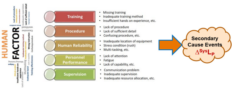
Figure B1 – Summary of Human Factors that can adversely impact a risk system’s likelihood of producing the primary effect event. Figure is adapted from Jinwoo Kim’s presentation, “Human Factor Control Strategy for Aseptic Manufacturing,” presented at PDA’s 2023 Aseptic Processing Conference.
Although ReRA does not model secondary factors as a risk’s primary cause, secondary factors can have a profound impact on the probability of a failure occurring. For many risks, identifying and analyzing secondary factors is the most important part of the risk analysis.
Secondary factors can be modeled as secondary risk relationships using the same SRS format as shown in Figure 1. As shown in Figure B2, the only difference is that the impact of the risk’s consequence is not to the primary risk’s subject but the risk’s primary system. Thus, the severity of a secondary risk is the change it causes in the primary system’s SysLP. Secondary factors can be controlled by adding a secondary risk system to decrease the likelihood of the secondary factor occurring. For example, if a secondary factor is an operator being interrupted by a cell phone call, the secondary risk system would be controlling the access to or presence of the operator’s cell phone while they are executing the procedure step.
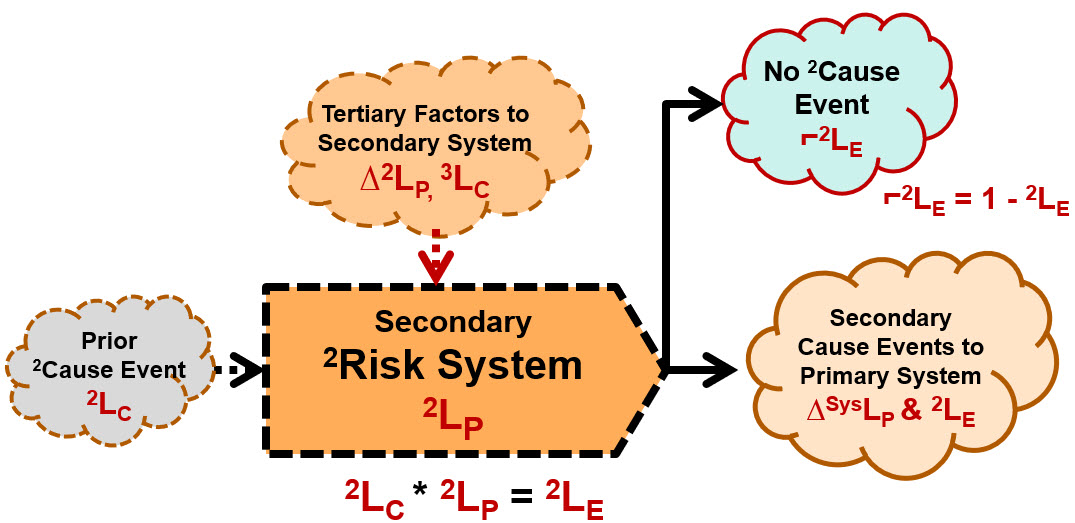
Figure B2 – Secondary Risks - Secondary factors to primary risks systems can be modeled the same way primary risks are modeled. To estimate and control the severity and likelihood of the secondary cause event, the secondary risk’s system can be evaluated and modified to achieve those objectives.
If you model secondary factors as risks, then you can both analyze and manage important secondary factors. By adding secondary risk elements to an SRS, you turn the risk’s SRS from a simple primary risk sequence to a network of risk systems that can be used to understand and better estimate the likelihoods of the primary sequence. By combining the primary SRS shown in Figure 2 with the SRS for secondary risk shown in Figure B2, very complex risks can be effectively modeled.
About The Author:
 Mark F. Witcher, Ph.D., has over 35 years of experience in biopharmaceuticals. He currently consults with a few select companies. Previously, he worked for several engineering companies on feasibility and conceptual design studies for advanced biopharmaceutical manufacturing facilities. Witcher was an independent consultant in the biopharmaceutical industry for 15 years on operational issues related to: product and process development, strategic business development, clinical and commercial manufacturing, tech transfer, and facility design. He also taught courses on process validation for ISPE. He was previously the SVP of manufacturing operations for Covance Biotechnology Services, where he was responsible for the design, construction, start-up, and operation of their $50-million contract manufacturing facility. Prior to joining Covance, Witcher was VP of manufacturing at Amgen. You can reach him at witchermf@aol.com or on LinkedIn (linkedin.com/in/mark-witcher).