
How To Achieve Continuous Flow In Med Device Manufacturing
By Darren Dolcemascolo, senior partner and co-founder, EMS Consulting Group

In the last two articles of our Thinking Lean series, we covered the value stream mapping methodology, which enables organizations to analyze and improve order fulfillment, product development, and even support value streams. In this article, we will talk about one of the key elements of a lean future state, creating continuous flow.
Achieving continuous flow is one of the most important principles of lean manufacturing. Yet, many people still do not understand what it truly means to achieve continuous flow. In this article, we will define continuous flow, outline the steps to creating continuous flow, and discuss a case example within the medical device field.
What is Continuous Flow?
Let us begin by discussing terminology. There are several basic terms used to describe continuous flow. The most common are as follows:
- Continuous flow
- One-piece flow
- Single piece flow
- Make one - Move one
- One-by-one production
- Flow manufacturing
Each of the above terms describes the same key element of the Toyota Production System, illustrated in the diagram below. As you can see, "Flow" is a shown as a key element of the pillar "Just In Time.”
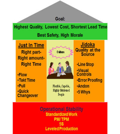 Thus, continuous flow is a tool that will help a manufacturer achieve true just-in-time manufacturing. That is, the right parts can be made in the right quantity at the right time. In the simplest of terms, continuous flow means that parts are moved through operations, from step-to-step, with no work in progress (WIP) in between either one piece at a time or a small batch at a time. This system works best in combination with a cellular layout, in which all necessary equipment is located within a (usually) U-shaped cell in the sequence in which it is used.
To achieve true one-piece flow, equipment must have basic stability:
- Highly capable processes — Processes must consistently produce good product. If there are many quality issues, a buffer of inventory is necessary to prevent too many line-down conditions.
- Highly repeatable processes — Process times must be repeatable, as well. If there is too much variation, continuous flow is impossible.
- Equipment with very high (near 100 percent) uptime — Equipment must always be available to run. If equipment within a manufacturing cell is plagued by downtime, one-piece flow will be impossible.
Continuous flow is usually associated with low-mix, high-volume manufacturing environments. However, one-piece flow also lends itself to high-mix, low-volume environments. It is usually achieved by creating mixed model or group technology cells, in which a number of products run through a particular cell utilizing continuous flow. Although every organization has unique challenges, one-piece flow can be achieved through proper application of the principle.
How To Implement Continuous Flow In 7 Steps
The first step in implementing a continuous flow cell is deciding which products or product families will go into the cells. The second step is determining the type of cell: Product-focused or mixed model. For product focused cells to work correctly, demand needs to be high enough for an individual product. For mixed-model cells to work, changeover times must be kept short; a general rule of thumb is that changeover time must be less than one takt time.
Third, calculate takt time for the set of products that will go into the cell. Takt time is a measure of customer demand expressed in units of time, and is calculated as follows:
Takt Time = Available work-time per shift / Customer demand per shift
Next, determine the work elements and time required for making one piece. In much detail, list each step and its associated time. Time each step separately, several times, and then use the lowest repeatable time. This lowest repeatable time must be sustainable throughout a work day; thus, the lowest repeatable time is defined as a reasonable repeatable time that can be achieved by a fully-trained operator.
Then, determine if the equipment to be used within the cell can meet takt time. Considerations here include changeover times, load and unload times, and downtime.
The sixth step is to create a lean layout. Using the principles of 5S (eliminating those items that are not needed and locating all items/equipment/materials that are needed at their points of use in the proper sequence), design a layout. Space between processes within a one-piece flow cell must be limited to eliminate motion waste and to prevent unwanted WIP accumulation. U-shaped cells are generally best; however, if this is impossible due to factory floor limitations, other shapes will do. For example, I have implemented S-shaped cells in areas where a large U-shape was physically impossible.
Finally, balance the cell and create standardized work for each operator within the cell. Determine how many operators are needed to meet takt time, and then split the work between operators. Use the following equation:
Number of Operators = Total Work content / Takt time
In most cases, an inconvenient remainder term will result (e.g., you will end up with Number of Operators = 4.4, or 2.3 or 3.6, instead of 2.0, 3.0, or 4.0) If there is a remainder term, it may be necessary to kaizen the process and reduce the work content. Other possibilities include moving operations to the supplying process to balance the line.
For example, one of my clients moved simple assembly operations from their assembly line to their injection molding operation to reduce work content and balance the line. In this case, the injection molding operator had enough time available to incorporate this assembly step into his operation.
After implementation is complete, one-piece flow must be sustained through regular auditing of standardized work. Standard work audits consist of monitoring adherence to standard work, deviations from standard work, and problem solving to determine how to further improve standard work.
Case Example: Continuous Flow At A Medical Device Manufacturer
The tools/principles utilized in this event were as follows:
- Standardized Work
- One Piece Flow / Cellular manufacturing
- 5S Principles
The current-state metrics for this particular operation were as follows:
- Average manufacturing cycle time: 10 days
- Productivity: 10 units/person per hour
- WIP: 5 days
- Mode of manufacturing: Batches of 50 units
- Over 300 ft. of product distance traveled
A kaizen team consisting of assemblers, manufacturing engineers, an area supervisor, and a few employees from outside the area was formed. After spending day one in training, the team began to observe and collect time data for each step in the manufacturing process. The team discovered significant waste in the process:
- Excessive batching of work at each stage caused extra handling.
- Out-of-cycle work: Operators were doing their own material handling and preparation.
- Excessive WIP as a result of batching
- Motion waste, due to improper tool and material presentation
- Layout was not conducive to one-piece flow; there was a long distance between operations. Operators were seated and had to get up and walk several steps to pass the product down to the next operation. Below is an example of how each operator had been positioned; each operator had a five-foot workbench onto which a lot of WIP could accumulate between operations.
- Lack of standardization: Each operator had his/her own way of performing a job step.

Using the principles of one-piece flow, standardized work, 5S, and SMED, the kaizen team instituted the following changes:
- The team developed standardized work sheets that identified each job step and the sequence and time associated with each step. This significantly reduced the variation between operators.
- The team developed a status and problem board that was used to communicate hourly progress (plan versus actual), as well as problems.
- The team developed and implemented a new cellular layout that was conducive to one-piece flow; it physically limited the amount of WIP between operations. Operators were positioned next to each other such that no walking was necessary to pass the workpiece down to the next operation. Below is an example of part of the revised layout with operations closer together.
- The improvements resulted in a 50 percent reduction in manufacturing cycle time, a 70 percent productivity improvement, and a 30 percent reduction in floor space used.

Conclusion
Continuous flow is one of the most important concepts within lean manufacturing. In most cases, a piece of a value stream can be transformed into a continuous flow operation. While flow is not always achievable for an entire door-to-door value stream, manufacturers must continually improve their processes in an attempt to get closer to true continuous flow. This will reduce necessary inventory levels, reduce manufacturing lead time, and improve customer service levels.